PROJECTS
Latest Projects
Senior Capstone Project
Melvin for his Senior Capstone project at Central Washington University decided to completely design, construct, and test a cheap and simple gripping assembly alternative that could be compatible with a pre-existing Instron TT-C testing machine available for the MET department of Central. The testing machine is non functional due to many missing devices including gripping assemblies. Adding gripping assemblies to the machine was a great start to getting the TT-C to adequate functionality for use by the MET department. The goals for the project were to design and create working gripping assemblies that were cheap and simple. These goals were met to an extent. The gripping assemblies were cheap to produce however very costly in man hours. Also, the gripping assemblies had a few design flaws that made them difficult to use.

DESIGN

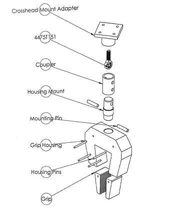
For Melvin's Senior capstone project, he designed, manufactured, and tested a pair of gripping assemblies for an Instron Tensile Tester. The tensile tester model was a TT-C which was innovated in the 1950's. Melvin designed the assemblies to withold a maximum of 20,000 pounds pulling force and to be able to grip tensile specimens from half inch to full inch cross sections. He also aimed to design the assemblies to be as small as possible. For his housing pieces, he designed with a design factor of 1.25. This is a very conservative value because the housing of the gripping assemblies are the largest parts in the assemblies.
Melvin decided to use 4140 OQT 400 for all of his parts except for the gripping wedges themselves. 4140 being heat treated with an OQT 400 was bringing the material to its maximum hardness, but because the parts were being designed for heavy static loads, Melvin determined that this was a good choice as opposed to spending the extra funds to use 4340. For the gripping wedges, S7 OQT 400 tool steel was used to get the desired hardness. The grips were designed to be at least 58 HRC so that they wouldn't deform under compression for even high carbon steels.
CONSTRUCTION
All parts were machined by Melvin using the facilities available at CWU which includes a fully functioning machine shop equipped with CNC mills and a CNC lathe. Melvin manually machined parts as well as wrote programs manually for CNC mills.
There arose many issues with machining the designed parts for the gripping assemblies. Some of the part designs were not feasible to manufacture given the available facilities to do so. As a result of this, there was an excessive amount of wasted time and money on machininig. For example, the housing component had to great a thickness to be milled in a practical way. Many end mills were broken machining this part and the total time spent on these components was appoximately 60 hours.
The parts were all heat treated bby Pacific Metallurgical in Kent, WA to OQT 400. The grippnig wedges were to be precision ground after heat treatment, but Melvin determined that the task would not be needed due to the already smooth surface finish on the faces that was left from a face mill during construction.
During construction, Melvin learned much about being a manufacturing engineer as well as learning the perspective of employees a part of the manufacturing process. By manufacturing his own designs, he truly was able to percieve the dificulty in understanding how to build his designs. Learning how to view a design project from these perspectives allowed Melvin to develop foresight in the design process.These skills could not have been learned without being physcally a part of the manufacturing processes of the design project
TESTING

The testing portion of the capstone project consisted of performing hardness tests on all components of the gripping assemblies, performing tensile tests on Aluminum, Mild Steel, and Medium Carbon Steel 1/2" cylindrical test specimens using the gripping assemblies, and performing non destructive testing methods on the gripping assemblies after use in tensile tests such as die penatrant and eddy current testing.
The hardness tests revealed the strength properties of each individual component. The components were heat treated to reach a specific tensile strength value of around 300 ksi. The hardness tests of each component shown that each component is to the designated strength. This allowed Melvin to have confidence in the strength properties of the parts going into the tensile tests. So if the tensile tests didn't go well, Melvin would know that it wasn't because of the strength properties or a faulty heat treatment.
During the tensile testing of an Aluminum specimen with the gripping assemblies, a fuse blew in the testing machine causing the assemblies to be stuck under laod until the fuse could be replaced. This allowed time for crack to form at the most vulnerable spot in the bottom housing component which led to its failure. This revealed a design flaw in the housing. Critical stress situations were not assumed correctly by Melvin at the threaded hole in the housing that was designated for the housing mount. The housing components then had to be redesigned to have two bands on the front and back of the specimen connecting the bottom of each tapered arm on each housing component. The bands were welded on.
SCHEDULE/BUDGET
During the course of the project, both the schedule and costs were underestimated. A total of $1144.86 were spent on the construction of the designs and over 500 hours were spent on the project as a whole. It was estimated that $795.72 would be spent on the project and 463 hours was the estimated man hours required. The extra cost accumulated for the project came from the added expense of replacing broken tool bits during the manufacturing process. The extra hours came from the added time to manufacturing the thick housing components. Feeds and speeds had to be slowed extremely and tool bits breaking during the process added a plethora of extra hours to the processes. Programs for the CNC machines had to be rewritten many times as well to find the optimum speeds and feed rates for the tooling to mill the thick housing components.